
 info@kunyi-cable.com


Phone


Top


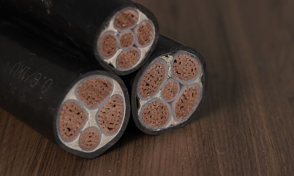
Power cable
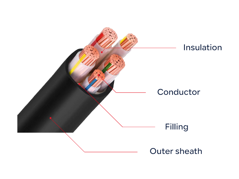
Cross-linked polyethylene insulated power cable has excellent thermomechanical properties, excellent electrical properties and chemical corrosion resistance. It also has the advantages of simple structure, light weight, and no limitation on laying height. It is a novel cable currently widely used in urban power grids, mines and factories.
 Related Products
1. Products Introduction
XLPE insulated power cables are superior in thermomechanical properties, electrical characteristics and chemical resistances.Theyare not only simple in construction and light in weight but also no limitation is required to the difference of levelin installation along theroute.This kind of up-to-date cables is widely used in electrical power nets in cities,mines and factories.
The insulation of the cable-XLPE is manufactured badopting a chemical or physical process of cross-inking of the molecularstructure. During the processthe cross inkable insulation is transformed from its linear chainstructure into a three-dimensional networkstructure owing to this substantive transtormation,the thermomechanical propertiesofthe cable insulation are greatly improved while itssuperior electrical characteristics remain unchanged.
The maximum permissible continuous conductor operating temperature of XLPE insulated power cables is 90'c,which is higher thanthat of paper,PVC,or PE insulated cables.The current ratings of the XLPE insulated cable further increase.
All the main equipment for producing XLPE insulated cables with rated voltages up to and including 26/35kv were imported formadvanced countries TROESTER of Germany and DAvlS of UsA equipped with X-ray eccentricity gauges, conductor preheaters and partial discharge equipment.
To meet the broad users needs. our company has successfully developed up-to-date flame-retardant type. ow smoke low halogentype. low smoke non-halogen type and watertight type XLPE insulated power cables. Cables of flame-retardant type. low smoke lowhalogen type,low smoke non-halogen type are suited for USB where emphasis is placed on special performanee of fame retardancysuch as high-rise buildings, hospitals, tunnels, power plants, petrochemical works, mines, etc; while the cables of watertight type are usedin the places where waterproof is strictlv realuired.
The above products, having been tested, are in contormity with the regurements ot the standards ot GB/2/06.2-2u2u、GB/T18380-2020、GB/T17650-1998、GB/T17651-1998、EC60502-2:2005、EC60332-200、EC61034-1997 and 1EC60754-1994.
2.Standard complied with
GB/T12706.2-2020 Powercables with extruded insulation and their accesseries for rated voltages form 1kV(Um-1.2kvup to and including35kV(Um=40.5kV).
1EC60502-2:2005 Power cables with extruded insulation and their accessories for rated voltages form ikV up to 30kv.
3.Service performance
Operating temperature Max.Permissible continuous operating temperature of conductors shall nol exceed 90'C.
Short circuit temperature of conductor ax.Short circuit temperature shall not exceed 250'℃(Max.sustaining period:not exceeding 5sec.).
XLPE Insulated Power Cable production technical process
Copper rod—wiredrawing—intertwist—extrusion (innerscreen,insulation ,outer screen)—undersheathextrusion—cable forming—partial discharge andvoltage withstand test—copper tapewrapped shield—wrapping of steel
tape—sheath extrusion—Partial discharge andvoltage withstand test—ready product storing
Min.bending radius at laying
| lteam | Single-core cable | 3-core cable | ||
| Without armour | With armour | Without armour | With armour | |
| Min .bending radius at laying | 20D | 15D | 15D | 12D |
| Min.bending radius near joint box and terminal box(bending carefully,e.g.dopting ofshaped slide) | 15D | 12D | 12D | 10D |
Remark:D-Overall diameter of cable
Laying temperature:The laying temerature is not less than 0°C
The laying method and reference parameters used to calculate the current carrying capacity of the cable: Laying in air: ambient temperature 40°C Laying in soil: ambient temperature 25°C The thermal resistance coefficient of the soil is 1.0°C·m/W
Layout of cables Layout of single core cables: in parallel (Spacing side by side: lD D=overall diameter) Mulitcore cables: laid
individully
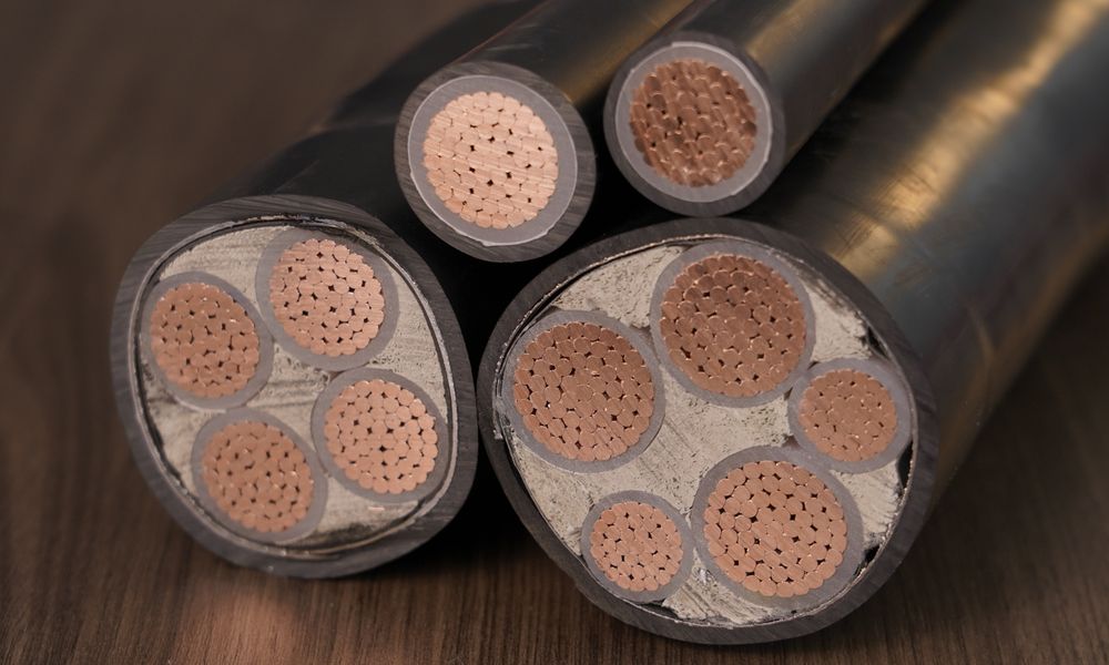
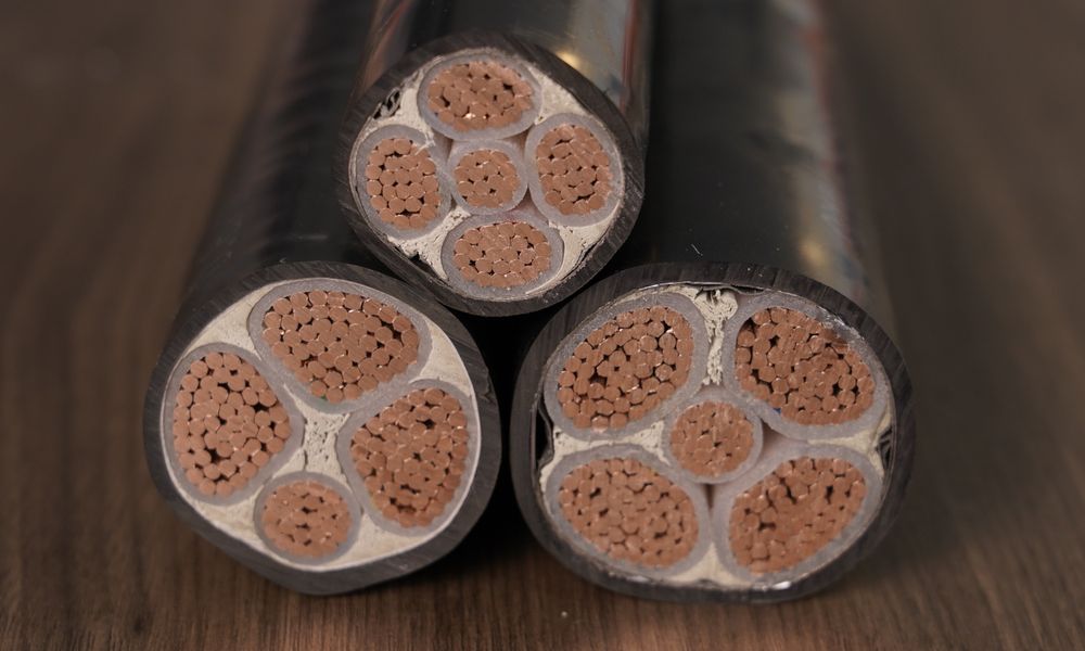
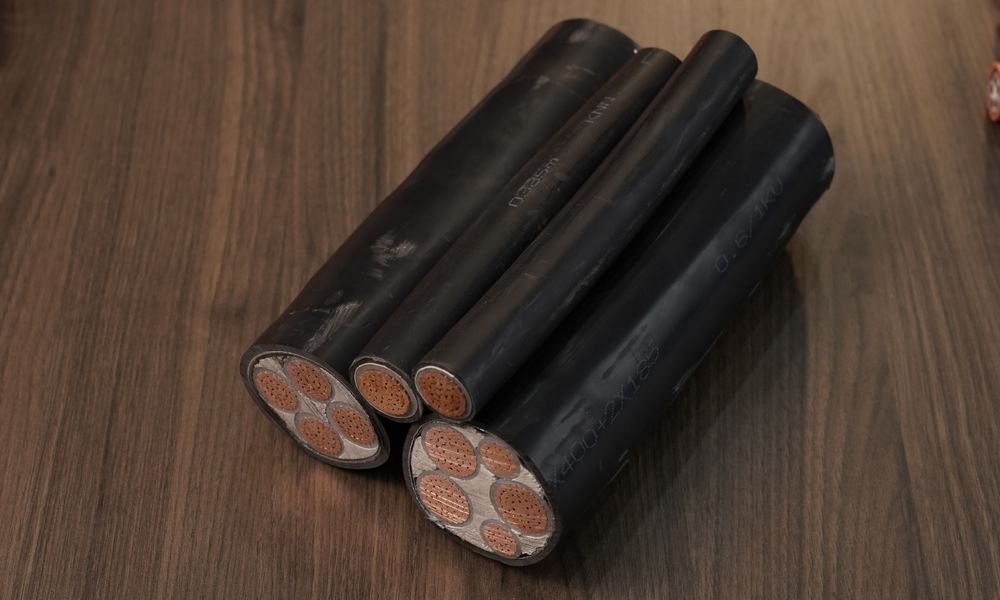
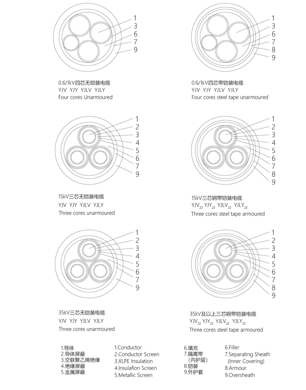
4.Constructed Profiles of the Products
5.Type,description and main applications
| Type | Description | Mainapplications | |
| Cu | AI | ||
| YJV | YJL | Copper or aluminum core XLPE insulated PVCsheathed power cable | For laying indoor and outdoor, unable tobear extemal mechanical force but thetractive force during laying. Laying singlecore cable in magnetic duct is not permis.sible. |
| YJY | YJLY | copper or aluminum core XLPE insulatedpolyethylene sheathed power cable | |
| YJV22 | YJLV22 | Copper or aluminum core XLPE insulated steeltape armored PVC sheathed power cable | For laying underground, able to bearexternal mechanical force, but unable tobear large pulling force. |
| YJV23 | YJLV23 | Copper or aluminum core XLPE insulated steeltape armored polyethylene sheathed powercable | |
| YJV32 | YJLV32 | Copper or aluminum core XLPE insulated thinsteel wire armored PVC sheathed power cable | For laying underground along route withdifferent level, able to bear external mechani-cal force and moderate pulling force. |
| YJV33 | YJLV33 | Copper or aluminum core XLPE insulated thinsteel wire armored polyethylene sheathedpower cable | |
| YJV42 | YJLV42 | Copper or aluminum core XLPE insulated thinsteel wire armored PVC sheathed power cable | |
| YJV43 | YJLV43 | Copper or aluminum core XLPE insulated thinsteel wire armored polyethylene sheathedpower cable | |
Remark:Steel tape armoured si ngle-core cables are used only in D.C,power supply system. lf they are used in A.Cpower supply system aluminum wires or other types of armour are adopted.
6. Scope of cables
| Type |
Nnmber of cores |
Rated voltages (kV) | ||||||||
| 0.6/1 | 18/3 | 3.6/6 |
6/6 6/10 |
8.7/10 8.7/15 |
12/20 | 18/30 | 21/35 | 26/35 | ||
| Nominal area of conductor(mm?) | ||||||||||
|
YJV YJLV |
1 | 1.5-800 | 10-800 | 10-800 | 16-800 | 25-800 | 35-800 | 50-800 | 50-800 | 50-800 |
| 2 | 1.5-240 | - | - | - | - | - | - | - | - | |
| 3 | 1.5-500 | 10-500 | 10-630 | 16-630 | 25-630 | 35-630 | 50-500 | 50-400 | 50-300 | |
| 4 | 1.5-500 | - | - | - | - | - | - | - | - | |
| 5 | 1.5-500 | - | - | - | - | - | - | - | - | |
|
YJV YJLV2222 |
1 | 16-800 | 10-800 | 10-800 | 16-800 | 25-800 | 35-800 | 50-800 | 50-800 | 50-800 |
| 2 | 2.5-240 | - | - | - | - | - | - | - | - | |
| 3 | 1.5-500 | 10-500 | 10-630 | 16-630 | 25-630 | 35-630 | 50-500 | 50-400 | 50-300 | |
| 4 | 1.5-500 | - | - | - | - | - | - | - | - | |
| 5 | 1.5-500 | - | - | - | - | - | - | - | ||
|
YJV YJLV3232 |
1 | 16-800 | 10-800 | 10-800 | 16-800 | 25-800 | 35-800 | 50-800 | 50-800 | 50-800 |
| 2 | 2.5-240 | - | - | - | - | - | - | - | - | |
| 3 | 1.5-500 | 10-500 | 10-630 | 16-630 | 25-630 | 35-630 | 50-400 | 50-300 | 50-240 | |
| 4 | 1.5-500 | - | - | - | - | - | - | - | - | |
| 5 | 1.5-500 | - | - | - | - | - | - | - | - | |
|
YJV YJLV4242 |
1 | - | 10-800 | 10-800 | 16-800 | 25-800 | 35-800 | 50-800 | 50-800 | 50-800 |
| 2 | - | - | - | - | - | - | - | - | - | |
| 3 | - | 10-500 | 10-630 | 16-630 | 25-630 | 35-630 | 50-400 | 50-300 | 50-240 | |
| 4 | - | - | - | - | - | - | - | - | - | |
| 5 | - | - | - | - | - | - | - | - | - | |
Flame retardant XLPE insulated cables,watertight XLPE insulated cables,low smoke low halogen and low smoke non-halogen XLPE insulated cables are also available on request.
The type designation for flame retardant cables is classified depending on the performance of buming test on bundled cables,separatelyexpressed by addition of derivation-ZRA,-ZRB or -ZR. lf no classification of fame retardancy or just derivation-ZR is indicated by the user,the flame retardant requirement is undemtood to reach class C,e.g. ZR-YJV,,-8.7/10 3x400
For Watertight type XLPE insulated cables, the derivation code is FS,e.g. FS-YJV:2-8.7/10 3x240
For low smoke non-halogen type XLPE insulated cables, the derivation code is WD-YJY22-8.7/103x300
7. Product constructions and main technical parameters
|
Core× Cross Section (mm2) |
Nom (mm) |
Hickness (mm) |
Tickness (mm) |
Nom.Sheath Thickness |
Dia.of Cable(By calculation) | Cable Weight (Approx) |
Max.D.C. Resistance of Conductor at 20℃ |
Current Rating(A) | |||||||||||||
| (mm) | (mm) | (kg/km) | (Ω/km) | Direct in Ground |
Run in Air | ||||||||||||||||
|
YJV YJLV |
YJV22 YJLV22 |
YJV32 YJLV32 |
YJV YJLV |
YJV22 YJLV22 |
YJV32 YJLV32 |
YJV | YJLV | YJV22 | YJLV22 | YJV32 | YJLV32 | Cu | AI | Cu | AI | Cu | AI | ||||
| 1×1.5 | 0.7 | - | - | 1.4 | - | - | 6 | - | - | - | - | - | - | - | - | - | - | - | - | - | - |
| 1×2.5 | 0.7 | - | - | 1.4 | - | - | 6 | - | - | - | - | - | - | - | - | - | - | - | - | - | - |
| 1×4 | 0.7 | - | - | 1.4 | - | - | 7 | - | - | - | - | - | - | - | - | - | - | - | - | - | - |
| 1×6 | 0.7 | - | - | 1.4 | - | - | 7 | - | - | - | - | - | - | - | - | - | - | - | - | - | - |
| 1×10 | 0.7 | - | - | 1.4 | - | - | 8 | - | - | - | - | - | - | - | - | - | - | - | - | - | - |
| 1×16 | 0.7 | 0.2 | 0.8 | 1.4 | 1.8 | 1.8 | 9 | 13 | 13 | 203 | 105 | 311 | 213 | 393 | 296 | 1.15 | 1.91 | 170 | 135 | 125 | 99 |
| 1×25 | 0.9 | 0.2 | 0.8 | 1.4 | 1.8 | 1.8 | 11 | 14 | 15 | 300 | 147 | 425 | 272 | 521 | 368 | 0.727 | 1.20 | 220 | 170 | 165 | 125 |
| 1×35 | 0.9 | 0.2 | 1.25 | 1.4 | 1.8 | 1.8 | 12 | 15 | 17 | 397 | 184 | 532 | 318 | 749 | 535 | 0.254 | 0.868 | 256 | 205 | 200 | 155 |
| 1×50 | 1.0 | 0.2 | 1.25 | 1.4 | 1.8 | 1.8 | 13 | 17 | 18 | 532 | 236 | 681 | 386 | 929 | 633 | 0.387 | 0.641 | 320 | 245 | 245 | 190 |
| 1×70 | 1.1 | 0.2 | 1.25 | 1.4 | 1.8 | 1.8 | 15 | 19 | 20 | 734 | 314 | 904 | 483 | 1188 | 767 | 0.288 | 0.443 | 395 | 305 | 305 | 240 |
| 1×95 | 1.1 | 0.2 | 1.25 | 1.5 | 1.8 | 1.8 | 17 | 20 | 22 | 988 | 406 | 1170 | 588 | 1482 | 900 | 1.193 | 0.320 | 475 | 370 | 375 | 290 |
| 1×120 | 1.2 | 0.2 | 1.6 | 1.5 | 1.8 | 1.8 | 19 | 22 | 24 | 1232 | 498 | 1425 | 692 | 1896 | 1163 | 0.153 | 0.253 | 545 | 420 | 435 | 340 |
| 1×150 | 1.4 | 0.2 | 1.6 | 1.6 | 1.8 | 1.8 | 21 | 24 | 26 | 1519 | 609 | 1724 | 814 | 2248 | 1339 | 0124 | 0.206 | 610 | 475 | 500 | 390 |
| 1×185 | 1.6 | 0.2 | 1.6 | 1.6 | 1.8 | 1.8 | 23 | 26 | 28 | 1880 | 747 | 2096 | 963 | 2659 | 1526 | 0.0991 | 0.164 | 695 | 540 | 580 | 450 |
| 1×240 | 1.7 | 0.2 | 1.6 | 1.7 | 1.8 | 1.9 | 26 | 28 | 31 | 2437 | 951 | 2670 | 1184 | 3306 | 1821 | 0.0754 | 0.125 | 810 | 630 | 685 | 636 |
| 1×300 | 1.8 | 0.2 | 1.6 | 1.8 | 1.9 | 2.0 | 28 | 31 | 34 | 3302 | 1162 | 3277 | 1417 | 3981 | 2121 | 0.0601 | 0.100 | 910 | 710 | 795 | 615 |
| 1×400 | 2.0 | 0.2 | 2.0 | 1.9 | 2.0 | 2.1 | 32 | 35 | 38 | 3872 | 1477 | 4158 | 1762 | 5206 | 2810 | 0.047 | 0.0778 | 1050 | 820 | 930 | 730 |
| 1×500 | 2.2 | 0.5 | 2.0 | 2.0 | 2.2 | 2.3 | 35 | 40 | 42 | 4920 | 1856 | 5647 | 2583 | 6446 | 3382 | 0.0366 | 0.0605 | 1190 | 940 | 1080 | 850 |
| 1×630 | 2.4 | 0.5 | 2.5 | 2.2 | 2.3 | 2.4 | 40 | 44 | 48 | 6306 | 2351 | 7116 | 3161 | 8431 | 4475 | 0.0283 | 0.0469 | 1350 | 1080 | 1250 | 1000 |
| 1×800 | 2.6 | 0.5 | 2.5 | 2.3 | 2.5 | 2.6 | 44 | 49 | 52 | 8008 | - | 8906 | - | 10352 | - | 0.0221 | - | 1520 | - | 1440 | - |
|
Core× Cross Section (mm2) |
Nom. (mm) |
Hickness Tape (mm) |
Tickness Wire (mm) |
Nom.SheathThickness | Dia.of Cable(By calculation) | Cable Weight(Approx) | Max.D.C. Resistance of Conductor at 20℃ |
||||||||||
| (mm) | (mm) | (kg/km) | (Ω/km) | ||||||||||||||
|
YJV YJLV |
YJV22 YJLV22 |
YJV32 YJLV32 |
YJV YJLV |
YJV22 YJLV22 |
YJV32 YJLV32 |
YJV | YJLV | YJV22 | YJLV22 | YJV32 | YJLV32 | Cu | AI | ||||
| 2×1.5 | 0.7 | - | - | 1.8 | - | - | 10 | - | - | 107 | 92 | - | - | - | - | 12.1 | 18.1 |
| 2×2.5 | 0.7 | 0.2 | 0.8 | 1.8 | 1.8 | 1.8 | 11 | 13 | 14 | 135 | 111 | 221 | 197 | 307 | 283 | 7.41 | 12.1 |
| 2×4 | 0.7 | 0.2 | 0.8 | 1.8 | 1.8 | 1.8 | 12 | 14 | 14 | 175 | 137 | 267 | 229 | 360 | 321 | 4.61 |
7.41 |
| 2×6 | 0.7 | 0.2 | 1.25 | 1.8 | 1.8 | 1.8 | 13 | 15 | 16 | 225 | 168 | 325 | 268 | 536 | 479 | 3.08 | 4.61 |
| 2×10 | 0.7 | 0.2 | 1.25 | 1.8 | 1.8 | 1.8 | 15 | 17 | 19 | 329 | 233 | 448 | 352 | 703 | 607 | 1.83 | 3.08 |
| 2×16 | 0.7 | 0.2 | 1.25 | 1.8 | 1.8 | 1.8 | 17 | 19 | 21 | 465 | 321 | 600 | 447 | 892 | 738 | 1.15 | 1.91 |
| 2×25 | 0.9 | 0.2 | 1.6 | 1.8 | 1.8 | 1.8 | 20 | 22 | 25 | 687 | 447 | 845 | 606 | 1331 | 1091 | 0.727 | 1.20 |
| 2×35 | 0.9 | 0.2 | 1.6 | 1.8 | 1.8 | 1.8 | 22 | 24 | 27 | 689 | 563 | 1072 | 737 | 1609 | 1275 | 0.524 | 0.868 |
| 2×50 | 1.0 | 0.2 | 1.6 | 1.8 | 1.8 | 1.9 | 25 | 27 | 30 | 1196 | 733 | 1394 | 931 | 2003 | 1540 | 0.387 | 0.641 |
| 2×70 | 1.1 | 0.2 | 1.6 | 1.8 | 1.9 | 2.0 | 29 | 31 | 34 | 1648 | 988 | 1886 | 1226 | 2603 | 1943 | 0.268 | 0.443 |
| 2×95 | 1.1 | 0.2 | 2.0 | 2.0 | 2.0 | 2.1 | 33 | 35 | 38 | 2204 | 1292 | 12471 | 1559 | 3542 | 2629 | 0.193 | 0.320 |
| 2×120 | 1.2 | 0.5 | 2.0 | 2.1 | 2.2 | 2.3 | 36 | 40 | 43 | 2743 | 1594 | 3451 | 2302 | 4244 | 3095 | 0.153 | 0.253 |
| 2×150 | 1.4 | 0.5 | 2.5 | 2.2 | 2.3 | 2.4 | 40 | 44 | 48 | 3384 | 1959 | 4164 | 2739 | 5480 | 4055 | 0.124 | 0.206 |
| 2×185 | 1.6 | 0.5 | 2.5 | 2.3 | 2.4 | 2.6 | 44 | 48 | 52 | 4182 | 2408 | 5039 | 3265 | 6453 | 4679 | 0.0991 | 0.164 |
| 2×240 | 1.7 | 0.5 | 2.5 | 2.5 | 2.6 | 2.7 | 50 | 54 | 58 | 5426 | 3099 | 6402 | 4076 | 8006 | 5679 | 0.0754 | 0.125 |
|
Nominal mm |
Thickness of mm |
Single core | ||||||||
| YJV、YJLV、ZR-YJV、ZR-YJLV |
YJV32、YJLV32、ZR-YJV32、ZR-YJLV32 |
YJV42、YJLV42、ZR-YJV42、ZR-YJLV42 | ||||||||
|
Outer diam mm |
Approximate weight |
Outer diam mm |
Approximate weight |
Outer diam mm |
Approximate weight | |||||
| CU | AI | CU | AI | CU | AI | |||||
| kg/km | kg/km | kg/km | ||||||||
| 25 | 4.5 | 23.1 | 740 | 585 | 30.1 | 1939 | 1784 | 34.9 | 3140 | 2986 |
| 35 | 4.5 | 24.1 | 862 | 646 | 31.7 | 2107 | 1890 | 35.9 | 3348 | 3131 |
| 50 | 4.5 | 25.4 | 1039 | 729 | 33.2 | 2358 | 2048 | 37.4 | 3651 | 3341 |
| 70 | 4.5 | 27.1 | 1273 | 840 | 34.9 | 2671 | 2238 | 39.3 | 4048 | 3614 |
| 95 | 4.5 | 28.9 | 1561 | 973 | 37.7 | 3372 | 2748 | 40.9 | 4461 | 3873 |
| 120 | 4.5 | 30.3 | 1830 | 1087 | 39.3 | 3737 | 2294 | 42.5 | 4868 | 4125 |
| 150 | 4.5 | 32.1 | 2165 | 1236 | 40.9 | 4148 | 3220 | 44.1 | 5326 | 4398 |
| 185 | 4.5 | 33.7 | 2530 | 1385 | 42.7 | 4622 | 3477 | 45.9 | 5849 | 4704 |
| 240 | 4.5 | 36.1 | 3110 | 1624 | 44.9 | 5311 | 3825 | 48.1 | 6602 | 5116 |
| 300 | 4.5 | 38.5 | 3736 | 1879 | 48.8 | 6652 | 4795 | 50.5 | 7421 | 5564 |
| 400 | 4.5 | 43.1 | 4853 | 2377 | 53.4 | 8078 | 5602 | 55.1 | 8920 | 6444 |
| 500 | 4.5 | 47.0 | 5930 | 2835 | 52.3 | 9414 | 6319 | 59.0 | 10317 | 7222 |
| 630 | 4.5 | 50.6 | 7240 | 3341 | 60.9 | 10964 | 7065 | 62.6 | 11924 | 8024 |
| 800 | 4.5 | 54.1 | 8904 | 3944 | 64.4 | 12879 | 7919 | 66.1 | 13954 | 8994 |
| 1000 | 4.5 | 60.3 | 11008 | 4703 | 70.4 | 15431 | 8983 | 72.3 | 16507 | 10083 |
| 1200 | 4.5 | 64.2 | 12971 | 5424 | 74.3 | 17626 | 10001 | 76.2 | 18820 | 11156 |
|
Nominal cross section mm |
Thickness mm |
三芯 | |||||||||||
| YJV、YJLV、ZR-YJV、ZR-YJLV | YJV22、YJLV22、ZR-YJV22、ZR-YJLV22 | YJV32、YJLV32、ZR-YJV32、ZR-YJLV32 | YJV42、YJLV42、ZR-YJV42、ZR-YJLV42 | ||||||||||
|
Outer diam mm |
Approximate weight |
Outer diam mm |
Approximate weight |
Outer diam mm |
Approximate weight |
Outer diam mm |
Approximate weight | ||||||
| CU | AI | CU | AI | CU | AI | CU | AI | ||||||
| kg/km | kg/km | kg/km | kg/km | ||||||||||
| 25 | 4.5 | 46.4 | 2361 | 1893 | 52.8 | 3360 | 3192 | 57.3 | 5840 | 5372 | 59.2 | 6775 | 6287 |
| 35 | 4.5 | 48.8 | 2772 | 2116 | 55.0 | 4109 | 3454 | 59.7 | 6404 | 5719 | 61.6 | 7296 | 6641 |
| 50 | 4.5 | 51.8 | 3357 | 2421 | 58.0 | 4771 | 3835 | 62.7 | 7213 | 6277 | 64.6 | 8122 | 7186 |
| 70 | 4.5 | 55.6 | 4131 | 2821 | 62.0 | 5671 | 4360 | 66.5 | 8218 | 6908 | 68.4 | 9247 | 7936 |
| 95 | 4.5 | 59.3 | 5036 | 3257 | 65.7 | 6672 | 4894 | 70.2 | 9352 | 7574 | 72.1 | 10500 | 8722 |
| 120 | 4.5 | 62.5 | 5919 | 3672 | 68.9 | 7639 | 5393 | 73.4 | 10460 | 8214 | 75.3 | 11624 | 9378 |
| 150 | 4.5 | 66.4 | 6998 | 4190 | 72.6 | 8787 | 5979 | 77.3 | 11838 | 9030 | 79.0 | 13024 | 10216 |
| 185 | 4.5 | 70.0 | 8189 | 4726 | 77.2 | 10247 | 6784 | 81.9 | 13482 | 10019 | 83.8 | 14758 | 11295 |
| 240 | 4.5 | 75.1 | 10043 | 5551 | 82.3 | 13045 | 8553 | 87.2 | 14999 | 10508 | 88.7 | 16951 | 12459 |
| 300 | 4.5 | 80.1 | 12013 | 6397 | 87.5 | 15244 | 9626 | 91.5 | 17597 | 11934 | 93.9 | 19436 | 13820 |
| 400 | 4.5 | 85.3 | 14795 | 7402 | 93.5 | 17695 | 10343 | 96.8 | 21109 | 13756 | 103.0 | 22440 | 15160 |
| 500 | 4.5 | 93.0 | 18381 | 8950 | 101.2 | 21503 | 12072 | 107.0 | 24589 | 15304 | 110.0 | 25961 | 16874 |
Our advantage

High transmission efficiency
Cables can efficiently transmit electrical energy and signals, providing stable power supply and communication transmission.

Strong anti-interference ability
The insulation layer of the cable can effectively isolate external electromagnetic interference and provide reliable signal transmission and power distribution.

Safe and reliable
The cables are professionally designed and manufactured, have good heat resistance, pressure resistance, and weather resistance, and can work safely and reliably under various environmental conditions.

Cost effective
Compared with other power transmission methods, such as aerial power transmission, cables have the advantages of small footprint and low line loss, saving resources and costs.

Flexible and diverse
Cables can be customized according to different needs, including the selection of conductor materials, insulation layer materials, number of cores, cross-sectional size and other parameters, and are suitable for different scenarios and applications.

Long life
High-quality cables are properly designed and manufactured to have a long service life, reducing maintenance and replacement costs.

Energy saving
Cables do not need to burn fuel when transmitting electrical energy, do not produce waste gas and environmental pollution, and meet the requirements of sustainable development.
High transmission efficiency
Cables can efficiently transmit electrical energy and signals, providing stable power supply and communication transmission.
Strong anti-interference ability
The insulation layer of the cable can effectively isolate external electromagnetic interference and provide reliable signal transmission and power distribution.
Safe and reliable
The cables are professionally designed and manufactured, have good heat resistance, pressure resistance, and weather resistance, and can work safely and reliably under various environmental conditions.
Cost effective
Compared with other power transmission methods, such as aerial power transmission, cables have the advantages of small footprint and low line loss, saving resources and costs.
Flexible and diverse
Cables can be customized according to different needs, including the selection of conductor materials, insulation layer materials, number of cores, cross-sectional size and other parameters, and are suitable for different scenarios and applications.
Long life
High-quality cables are properly designed and manufactured to have a long service life, reducing maintenance and replacement costs.
Energy saving
Cables do not need to burn fuel when transmitting electrical energy, do not produce waste gas and environmental pollution, and meet the requirements of sustainable development.
Understanding Requirements
Providing Custom Solutions
Providing Samples and Technical Support
Ordering and Production
Logistics and After-Sales Service

Looking forward to hearing from you!
CONTACT US
1. Call us
2. Send an email
3. Leave a message
4. Add WeChat or Whatsapp